- Instant email delivery
- Global licenses
- Secure checkout
- 24/7 customer support
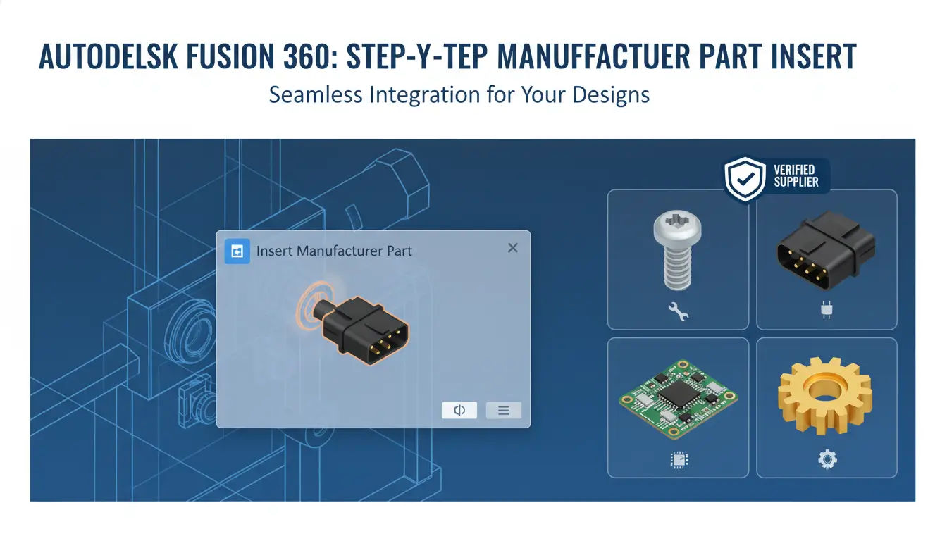
autodesk fusion 360 gives designers and engineers access to manufacturer parts—predefined, supplier-backed 3D models and metadata you can drop straight into assemblies. These parts are more than geometry: they carry part numbers, specifications, tolerances, material callouts and sometimes procurement details. Using manufacturer parts in early-stage design reduces guesswork, speeds validation, and ensures the CAD model aligns with real-world components used in production.
Adopting verified supplier components improves downstream workflows: bill of materials (BOM) accuracy, CNC toolpath reliability, assembly checks, and purchasing efficiency. Because the models match vendor datasheets and footprints, you avoid costly rework from mismatched fasteners, connectors, or electronic modules. If you need deployment or licensing information, consider resources like the Fusion 360 with FeatureCAM offering, and for broader platform context see Autodesk product design & manufacturing.
Verified supplier components deliver traceability and up-to-date specifications so designs reflect purchasable, tested items. In practice that means faster quoting, fewer prototype iterations, and a smoother handoff to procurement and contract manufacturers. Standardized, supplier-verified parts enable accurate mass properties and finite element inputs, improving simulation fidelity. They also simplify compliance checks—electrical ratings, material certifications, and traceability are often embedded in the part metadata. By building assemblies from manufacturer parts you create a single source of truth from concept through production, shorten time-to-market, and reduce risk associated with incorrect or ambiguous components.
autodesk fusion 360 users should confirm they have the correct subscription and that any required libraries or add‑ins are enabled before importing manufacturer parts. Doing these checks up front prevents failed imports, missing features, or unexpected CAM limitations that interrupt a build or prototype cycle.
Begin by signing into your Autodesk account and verifying your license type — hobby, commercial, or education — because access to some manufacturer content and CAM features depends on entitlement. In Fusion 360, review the Data Panel to confirm team and project permissions, then open Preferences → Preview Features/Add‑ins to enable manufacturer libraries, content packs, or third‑party add‑ins you plan to use. If your company uses managed libraries, ensure IT or an admin has granted access and that library paths are correctly mapped to your workspace.
Also confirm cloud storage and project workspace settings so downloaded manufacturer parts land in the intended project, and verify you have sufficient cloud credits or storage if your workflow uses cloud translation services. After installing a parts library or add‑in, restart Fusion 360 and test by inserting a known manufacturer component. For more on available editions and licensing, see the Fusion 360 editions and licensing page.
Quick checklist: sign in (top-right) and confirm the active product/seat under Account or About; open Preferences → Add‑ins/Preview Features and toggle any manufacturer libraries or vendor add‑ins on; then restart Fusion 360. In the Data Panel check Libraries or Insert menus to confirm manufacturer parts are visible. If a library is missing, follow the vendor’s install steps or have your admin push the library to the team workspace.
If a manufacturer part still won’t import, try clearing cache, testing in a new project, or contacting your administrator. For official guidance on product capabilities and licensing comparisons, refer to Autodesk’s product design & manufacturing overview.
Supplier libraries and add-ins give you access to genuine parts and manufacturer metadata right inside Fusion 360. To enable them, open the Data Panel, go to Add-Ins, and turn on the McMaster‑Carr or Manufacturer Content Library. If your organization uses cloud libraries, enable them in your Autodesk account settings so parts sync across devices and teams.
Once enabled, use the Library Browser or Insert > McMaster to search by part number, manufacturer, or spec. Install or update content packs from Add-Ins and restart Fusion 360 if new parts don’t appear immediately. Manufacturer libraries supply reliable geometry and metadata for BOMs and CAM, so prefer them when accuracy matters. For more on Fusion 360 features and bundles, see the Autodesk Fusion 360 with FeatureCAM page. For account and product details visit Autodesk product pages.
When you need an exact off‑the‑shelf component, streamline the process using autodesk fusion 360’s built‑in tools and a few reliable supplier sites. Start by identifying the part number, size, and key specs (material, finish, tolerance). With those in hand you can quickly filter Content Center libraries, Manufacturer tab entries, or external catalogs to find a model that matches engineering requirements and procurement details.
Use the Content Center for standard fasteners and families, and switch to the Manufacturer workspace when you need CAM‑ready geometry and supplier metadata. Search by manufacturer name or part number, preview the 3D model, and confirm dimensions in the browser before importing. If a part isn’t available, create a custom library entry and save a parametric family so future designs reference the same component. For larger projects, consider adding a commercial library or linking to supplier STEP files for the highest fidelity.
Always cross‑check the CAD geometry against the supplier’s datasheet and download native STEP/IGES or neutral formats to avoid reprojection errors. Verify thread forms, seating faces, and mounting interfaces in an assembly context. When you need integrated toolpaths or post‑processing options, the Manufacturer workspace will let you attach stock, define setups, and ensure the part will machine correctly. For an expanded feature set or bundled options, see the Fusion 360 with FeatureCAM offering from SoftAuthentic and check Autodesk’s Product Design & Manufacturing overview for official guidance.
Download native CAD formats (STEP, SAT, or Fusion Archive) from supplier sites or grab direct links from the Fusion library to bring parts quickly into your assembly. Start by saving the supplier file to a known folder or using the Data Panel’s “Upload” or “Insert from URL” features so the geometry and metadata are preserved. Prioritize STEP or Fusion Archive when possible — they keep history, units, and mating geometry intact; SAT is a good neutral fallback for solid bodies.
Before finalizing the import, confirm units and orientation, heal small gaps with automatic repair tools, and simplify overly dense meshes or imported features that will slow down editing. If you need an integrated solution for machining or downstream workflows, consider the Fusion 360 package with CAM support available here: Fusion 360 with FeatureCAM. For official format support and cloud library details, see Autodesk’s product design overview: Autodesk product design and manufacturing overview.
In Autodesk Fusion 360, placing a downloaded or library component into your active design is straightforward: use Insert > Insert Derive or Insert into Current Design to pull the part in while preserving source relationships. Start by opening the destination design and choosing the file or library part you want to add. In the Insert dialog select whether to bring it in as a linked-derived component (maintains updates) or as a static insert. Pick the correct placement plane—top (XY), front (XZ) or right (YZ)—so the component’s face aligns with the assembly origin.
Before confirming, check orientation using the preview gizmo: flip axes if the part is mirrored or rotated, and verify units and scale. If the part should be an independent component, enable “As Component” and set the component origin to match your assembly origin or a selected face. After insertion, use Move/Copy or Modify > Align to fine-tune position and use joints to define functional relationships. If the manufacturer part comes from a library, verify metadata and material properties, then consider placing it with the origin at a convenient datum so subsequent mates and joints are simpler.
Need the installer or a packaged library? Get the Fusion 360 download and library package from this source.
autodesk fusion 360 users should follow a short checklist after inserting a part: confirm the insertion plane, align component origin to assembly datum, and set the initial joint type (Rigid for fixed parts). Use Move/Copy with joint origin preview to snap to faces or edges, and capture position if you need to retain the temporarily placed location. If orientation is wrong, the Align tool or Modify > Flip option will correct mirroring without reimporting. Finally, run a quick interference check and save the assembly version.
For more about Autodesk’s product design tools and workflows, see the official Autodesk product design & manufacturing overview.
Choose “Insert into Current Design” when you need to place a model or file into an assembly as a separate component—perfect for positioning, applying joints, and preserving independent timelines. Insert is straightforward for assembly-level placement and treating the incoming part as a distinct item.
Choose “Derive” when you need geometry copied into an existing component while keeping associative references. Derive pulls sketches, faces, or bodies into the target component and maintains links so updates to the source propagate. It’s the right choice for dependent features, shared construction geometry, or when you want to preserve design intent across parts.
Keep an eye on circular references: decide which part is the source and which is the consumer before deriving. For practical guidance, see the Fusion 360 product page on SoftAuthentic and Autodesk’s product design & manufacturing overview.
Accurately locating a manufacturer part in an assembly requires a mix of intent and the right tools: joints to define motion and relative position, rigid groups to lock components together, and assembly constraints to control degrees of freedom. Begin by inserting the part as a component and aligning its origin or a named datum to a mating feature on the host assembly. Use small construction geometry (planes, axes, points) to create predictable attachment references rather than relying on face-to-face guessing.
Create joints when you want defined motion or a precise mate—choose revolute, slider, or planar as appropriate. For parts that must remain fixed relative to one another, a rigid group or a rigid-type joint simplifies management and reduces solver effort. Avoid overconstraining: prefer one positional joint plus motion limits rather than multiple redundant constraints that can produce solver errors.
Use joint origins and named connectors to make future edits straightforward. Test the assembly by animating degrees of freedom, applying motion limits, and running interference checks. If the part comes from a manufacturer file, verify its coordinate system and, when necessary, apply an “as-built” joint to lock its current pose before refining alignment. For licensing or to explore advanced assembly features in Fusion 360, see the Fusion 360 with FeatureCAM product page.
In autodesk fusion 360, prefer joints over legacy mate constraints for clearer intent and better motion definition. Name every joint and joint origin, ground a reference component during setup, and use rigid groups when multiple parts form a single subassembly. Leverage motion limits and contact sets to simulate real behavior and catch interference early. When fine alignment is required, create a temporary construction plane or a point pair and snap the joint origin to it—this reduces iterative dragging and preserves parametric edits. For official guidance on workflows and product capabilities, see Autodesk’s product design & manufacturing overview.
In autodesk fusion 360, prefer the Joint command when you need repeatable, contact-based connections and Align for quicker planar placement. Joints accept faces, edges, and points, so choose geometry that represents the true mating surfaces for reliable motion and assembly behavior.
See the available Fusion 360 bundles like Fusion 360 with FeatureCAM and explore official guidance on the Autodesk product pages.
Editing properties, materials, and parameters is a critical step to make sure your CAD data reflects manufacturing intent, costing, and assembly documentation. Start by updating part metadata — part numbers, revision, supplier, and custom attributes — so the bill of materials (BOM) exports correctly and downstream systems receive consistent information. Assign materials not just for visual realism but for accurate mass, center of gravity, and CAM/toolpath considerations. Use appearance assignments separately when you need different visual finishes without changing physical material properties.
Adopt a single-source strategy: store standard materials and parameter templates in a library, reference them across components, and keep parameter names consistent (thickness, clearance, wall, etc.). Parametric dimensions are your control knobs; expose only the model parameters that designers or engineers should change, lock the rest, and document the intent in the part properties so changes remain predictable.
When preparing for production, validate mass and cost estimates by running a quick properties check and exporting the BOM. If you need integrated CAM or toolpath support, consider product bundles that include Fusion 360 capabilities—see the Fusion 360 with FeatureCAM offering for streamlined workflows: Fusion 360 with FeatureCAM product page. For broader product design guidance from the software publisher, review Autodesk’s product design resources: Product Design & Manufacturing overview.
Keep parameters named clearly and grouped by function (geometry, tolerance, material). Use user parameters for variables that should appear in design tables or driven features, and add descriptive notes in the properties panel so non-authors can understand change impact. When assigning materials, prefer entries from a controlled library to ensure consistent density and finish values used in mass properties and cost calculations.
Before finalizing, run a properties report and export the BOM in the format your ERP or purchasing system expects. Small efforts in naming and library discipline save time and reduce errors during procurement and manufacturing handoff.
To ensure your Fusion BOM and any exported manufacturing files carry the correct supplier information, update part numbers and metadata at the component level. Start by selecting the component in the Browser, right‑clicking and choosing Properties. Populate fields such as Manufacturer, Manufacturer Part Number, Supplier, Supplier Part Number and URL — these fields feed the Fusion BOM and CSV/ERP exports.
Keep supplier links consistent: use a single canonical URL per supplier entry to avoid duplicate records in the BOM, and standardize part numbering formats (e.g., SKU vs. MPN). After changes, regenerate the BOM (Utilities > BOM) and review the export preview to confirm mappings. For teams, document the metadata schema and lock critical fields with permissions to prevent accidental edits.
For guidance on product workflows, see the Fusion 360 bundle page for setup recommendations and Autodesk’s product design resources for BOM export formats.
When you work with autodesk fusion 360 projects, common issues often stem from scale mismatches, missing references, or unsupported file types. Start every import by confirming units and scale—mismatched units are the single most frequent cause of incorrect geometry. If geometry looks wrong, toggle display of origin and inspect transform values before remodeling. For missing references, relink external components or reattach them by opening the parent assembly and using the “Find missing files” or equivalent workflow.
Unsupported formats can usually be remedied by exporting to a neutral exchange format (STEP/IGES for solids, OBJ/STL for meshes) from the originating application. Keep a short checklist: verify units, inspect origins, try a neutral format, run a mesh/solid repair, and re-export. Maintain an organized parts library with clear naming, version notes, and a single source of truth—store master libraries on a shared server or cloud location and avoid local ad-hoc copies.
For broader product guidance and updates, consult Autodesk’s product design resources for compatibility and format guidance. For package details or licensing options for Fusion 360 with add-ons, see the Fusion 360 package information on our site.
Quick fixes: enable unit display, use the Scale tool for uniform adjustments, and run “Repair” on imported meshes. When references break after moving files, relink using absolute paths temporarily, then migrate to relative paths within a controlled library. For collaboration, adopt version control: tag milestone files, use a cloud project or PDM when available, and keep commit messages that note format changes or reference updates. Regularly export critical builds to a neutral archival format (STEP/parasolid) to future-proof designs and speed recovery if a library becomes corrupted.



 Autodesk
 Design Softwares
 CorelDraw
 Affinity V2
 Microsoft & Windows
 Windows
 Microsoft 365