- Instant email delivery
- Global licenses
- Secure checkout
- 24/7 customer support
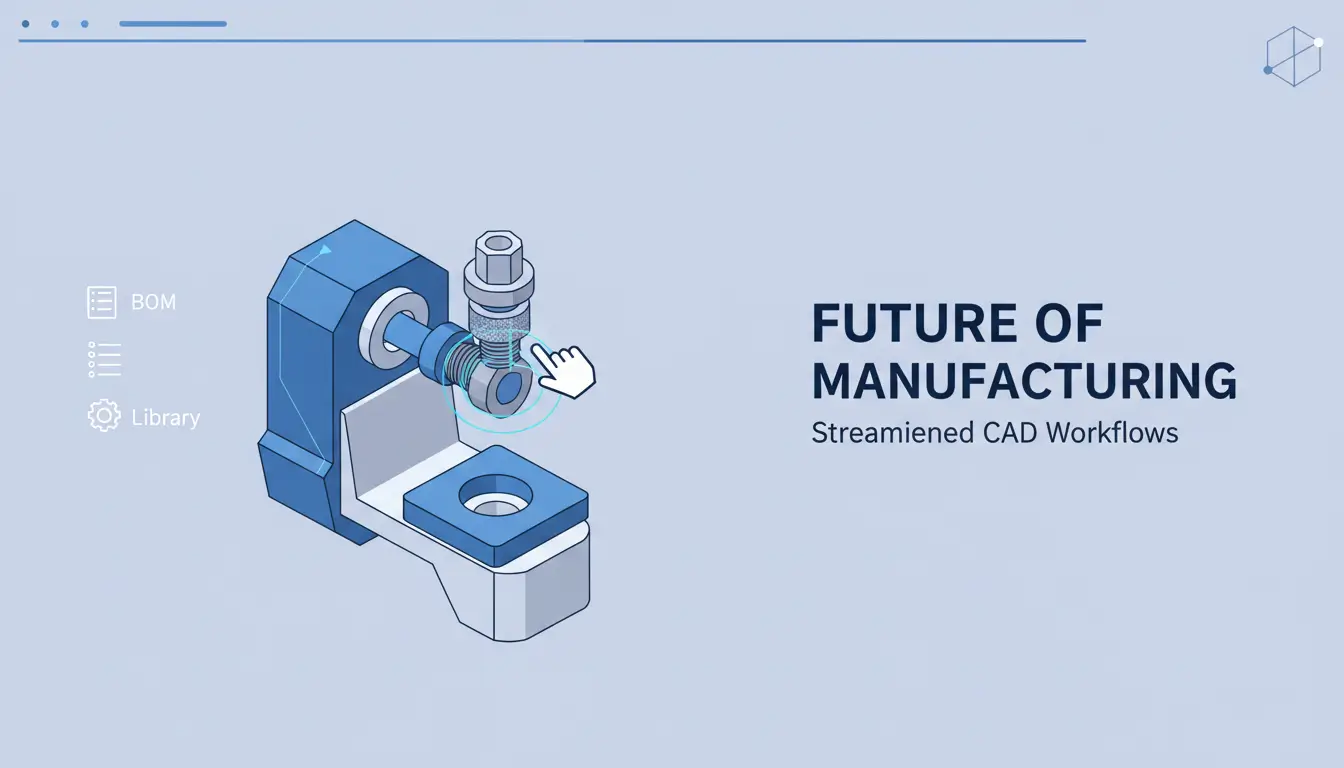
In autodesk fusion 360, a “manufacturer part” is a ready-made component—either a supplier-supplied CAD file or a library entry—designed to be dropped straight into your assembly. Rather than modelling a standard fastener, motor, or connector from scratch, you place a manufacturer part that already carries geometry, mounting features and critical metadata such as part number, supplier, material, and cost. This saves modelling time, improves fit and tolerance confidence, and feeds accurate information into bills of materials (BOMs) and procurement workflows.
Manufacturer parts can be parametric or fixed, and many come from verified supplier libraries or from shared company repositories. When used consistently they help standardize designs, reduce manual entry errors, and make change management easier because the component’s identity and lifecycle data travel with the model. You can also map manufacturer parts to procurement tags so downstream teams immediately know ordering options and lead times.
For licensing, downloads, or additional tooling bundles, see the Fusion 360 product offering on SoftAuthentic.
Using manufacturer parts in assemblies shortens the path from concept to production. Designers avoid redundant modeling work, simulation inputs reflect real-world geometry, and manufacturing receives clean BOM exports that include supplier references. In practice this means fewer design iterations tied to sourcing, faster design reviews, and clearer handoffs to buyers and vendors. For official product and ecosystem information, consult Autodesk’s product design & manufacturing overview.
When working in autodesk fusion 360, finding accurate manufacturer parts quickly keeps design momentum moving. Common sources are Fusion’s built‑in McMaster‑Carr integration, vendor websites that let you download neutral formats (STEP, IGES, Parasolid) or native CAD files, and manufacturer CAD libraries or portals such as TraceParts and GrabCAD. Vendor sites often provide multiple file types and technical metadata (weight, material, and tolerances) — download the format that best preserves geometry and parametrics for your workflow.
Practical checks: verify units and coordinate systems immediately after import, confirm fit and tolerance data from datasheets, and prefer STEP/Parasolid for broad compatibility when native files aren’t available. For production, simplify long, detailed vendor geometry before CAM or simulation to reduce file size and avoid unnecessary features. If you want a focused solution for CAD/CAM workflows, see the Autodesk Product Design & Manufacturing overview for more on Fusion and related tools.
For integrations specific to Fusion, product bundles and add‑ons can extend part libraries and machining workflows; if you use Fusion 360 on Windows with featureCAM, consider the official Fusion package offerings for streamlined setup.
Fusion’s McMaster‑Carr link lets you insert common fasteners and components directly into your design, saving the download/import step. When vendors provide STEP, IGES, or Parasolid files, import the neutral file and check that origin and orientation match your assembly. Manufacturer portals like TraceParts and GrabCAD are excellent for uncommon or branded parts; always cross‑check part numbers and revision history. If a vendor supplies only native formats not supported by Fusion, request a STEP/Parasolid or use a trusted conversion tool.
autodesk fusion 360 works best when you start with neutral, solid CAD formats rather than raw meshes. For parametric editing and reliable feature history, prefer STEP (.stp/.step), IGES (.igs/.iges) or Parasolid (.x_t/.x_b). These exchange formats preserve topology and make boolean, sketch and parametric operations predictable.
If you must use an STL, convert the mesh to a BRep before heavy editing (Fusion 360 has mesh-to-BRep tools but they struggle with very dense scans). For official product details, see the Fusion 360 with FeatureCAM page and the Autodesk product design & manufacturing overview for format support and workflow recommendations.
In autodesk fusion 360 the fastest way to add commercial hardware or stocked parts is the built‑in McMaster‑Carr connector. Use Insert > Insert McMaster‑Carr Component (or the same option from the Insert menu) to open a web dialog, browse McMaster’s catalog, and push a selected part straight into your active design. This avoids manual downloads, file conversion, or hunting for STEP files and keeps your assembly placement and component naming consistent. If you need a packaged Fusion workflow, see the Fusion 360 product bundle for Windows for additional CAM and library options.
From the Insert McMaster‑Carr Component dialog, search by keyword or paste a McMaster part number. Preview sizes and materials in the dialog, then click Insert — Fusion downloads a neutral CAD representation and places it in the current component. Use the Place handle to position or accept default placement; the part comes in as a linked component so you can edit properties, change units, or suppress appearances. Threads and small details are often simplified for performance; if you require full geometry, edit the imported body or replace it with a downloaded STEP. The workflow is immediate and reliable, and for broader product design resources you can refer to Autodesk’s product design & manufacturing overview for guidance.
Use this quick workflow to place McMaster‑Carr hardware into your assembly with minimal fuss.
Tip: components dropped from McMaster‑Carr often import as a single body—right‑click the item in the Data Panel to edit appearance, bodies, or convert to a component if you need separate occurrences.
For product details and licensing, see the Fusion 360 product page on this site and Autodesk’s product design overview.
Fusion 360 product page · Autodesk product design overview
autodesk fusion 360 lets you quickly bring vendor geometry into your assemblies by importing neutral CAD formats. Start by downloading the STEP, IGES or Parasolid file from the component vendor website and saving it to a known folder. In Fusion, open the Data Panel, choose the project folder, then click the Upload button and select the file. Once uploaded you can open the uploaded design or right‑click its entry and choose Insert into Current Design or Derive — Insert places the part as a component, Derive pulls it in as a linked component you can reference or update. Check units and orientation on import, simplify overly complex solids if needed, and consider converting imported bodies into components for easier joints and motion work.
Need a Fusion installer or licensing option? See Fusion 360 download & licensing from a trusted supplier.
Insert is best when you want a static part placed into your active design: open the uploaded design and choose Insert into Current Design to position and constrain it directly. Derive is preferable when you want a maintained link to the source geometry — changes to the source file can be propagated. After inserting or deriving, verify occurrences in the Browser, fix any scale/unit mismatches under the Modify menu, and use Move/Copy to orient the part. For manufacturing, switch to the Manufacture workspace once the component is positioned. If you encounter mesh issues or missing faces, run repair tools or re-export the STEP/IGES from the vendor with higher fidelity. For product platform details visit Autodesk Product Design & Manufacturing.
Quick, practical instructions to add a downloaded model into Fusion 360 and place it in an assembly. These steps assume you already have the file saved locally and Fusion 360 open.
If you need product details or licensing options, see the Fusion 360 product page for offerings and system notes, or visit Autodesk’s product-design overview for broader context.
Fusion 360 product page — Autodesk product-design overview
In autodesk fusion 360 you have two complementary workflows for placing components: use Move/Copy for fast, unconstrained placement or create Joints and As‑Built Joints to fully constrain motion. Move/Copy is ideal for rough layout and temporary adjustments; once you know the intended relationship, convert that placement into a joint so the constraint lives in the timeline. Joints (rigid, revolute, slider, etc.) control degrees of freedom by defining joint origins and motion types, while As‑Built Joints capture the existing relative position without repositioning geometry.
For precise mating, combine Align with Contact Sets: Align snaps faces, edges, or vertices to establish clean geometry alignment before committing a joint. Contact Sets are useful when you need collision detection without explicit joints, or to allow parts to interact while preserving a desired clearance. Use origin geometry and construction planes to define repeatable references, ground components to lock a base part, and group rigid components to reduce joint count. When troubleshooting, inspect joint degrees of freedom and edit joint origins directly in the timeline. For a guided download or licensing option, see the Fusion 360 product page on SoftAuthentic.
For broader workflow guidance and examples of assemblies and constraints, Autodesk’s product design resources provide detailed documentation and tutorials.
Start by using Align to register exact faces or edges, then create a joint type that matches the intended movement: rigid for fixed parts, revolute for hinges, slider for linear motion. If the component is already placed, choose As‑Built Joint to lock the current relationship without moving geometry. Use Contact Sets when you want parts to interact physically but not be fully constrained; set small clearance and enable collision detection to validate fit. Finally, ground the primary component or capture the position to prevent unintended drift, and review joint limits to ensure the assembly behaves as designed.
When working in autodesk fusion 360, the workflow differs depending on whether you imported a mesh (STL) or a solid. For mesh parts, switch to the Mesh workspace and use Modify → Mesh to BRep to create editable solids—but watch face-count limits: very dense meshes can fail to convert or create extremely heavy geometry. Before conversion, simplify the mesh with Modify → Reduce or repair problem areas with Mesh → Repair; focus on the region you actually need to model parametrically so conversion stays manageable. If the mesh is still too dense, export smaller sections or remesh at a coarser resolution.
For native solid imports, prefer the Modify toolset (Combine, Split Body, Stitch, Delete Face) to clean and prepare geometry. To maintain a live link to an external model so changes can propagate, use Create → Derived Component (or the equivalent Create Derived workflow) to bring in a linked component rather than a static body. After converting or cleaning, turn bodies into components and sketch directly on faces or planes to build true parametric features.
For more on acquiring the right Fusion 360 bundle and integrations, see the Fusion 360 product page.
Convert meshes in small steps: isolate the area you need, reduce faces, then Mesh to BRep. After conversion, expect multiple bodies—use Combine or Merge to simplify and Delete Face or Stitch to close gaps. Create sketches on the newly converted faces and apply Extrude, Fillet, and Parametric constraints to rebuild intent.
When working with updated source geometry, bring solids in as a derived component so edits in the source file propagate into your assembly without breaking parametric features. For official guidance and best practices on product workflows, consult Autodesk’s product design & manufacturing overview.
When working in autodesk fusion 360 you should populate part properties early—manufacturer, manufacturer part number, supplier name and supplier part number—so downstream BOMs and procurement are accurate. In the part or component properties dialog add vendor contact, lifecycle state and any traceability tags you use. Use Manage > Bill of Materials to include the supplier part into assembly BOMs, make it a purchased item or link it to existing library parts, and export standard CSV or Excel BOM reports for procurement.
Before finalizing, verify units and tolerances: check model units (mm/in) and manufacturing tolerances against design intent, convert or lock units as needed, and document critical dimensions in the drawing. Confirm the supplier model’s license and permitted use to avoid IP or redistribution issues. Also confirm mass, center of gravity, hole/fastener fit, and any required simplifications for CAM or FEA. If you need product details or downloads, see the Fusion 360 product page for features and licensing options.
Autodesk product design & manufacturing
autodesk fusion 360 import problems are usually solvable with a few focused checks. If your model won’t load, first confirm the file format and units — mismatched units or unsupported formats are the most common causes. Try opening the file in its native CAD viewer to verify geometry integrity and to see whether the source app offers a cleaner export. For mesh-based imports, simplify high‑density meshes or decimate polygons before importing; for solids, re-export as STEP, IGES, or Parasolid to preserve topology.
Other practical checks: ensure there are no duplicate bodies or zero‑thickness faces, reduce assembly complexity by importing subassemblies one at a time, and watch for unusually large coordinate values that can cause precision issues. If Fusion 360 shows conversion errors, use the Repair/Boundary tools and consider converting meshes to B‑Rep only when they are low‑poly. Keep a local copy of the original file in the Data Panel so you can track versions and revert if an import attempt corrupts the workspace.
If you need a replacement installer or alternate packaging, see Fusion 360 distribution options provided by this reseller for different bundles and licensing setups.
For official documentation and troubleshooting articles, consult the Autodesk product resources.
When an import fails, try these quick fixes in order: (1) reopen the source file and export as STEP with default tolerances, (2) check and unify units (mm vs in), (3) reduce mesh density or export a CAD solid instead of an STL, (4) import parts individually to isolate the problematic body, and (5) run Fusion 360’s Repair commands or convert only small meshes to B‑Rep. If geometry appears corrupt, open the file in the native CAD app and run its healing tools before re-exporting.
If problems persist, capture a short screen recording and export the problematic file to a ZIP, then contact support with the files attached; including the Data Panel copy and a step-by-step reproduction makes diagnosis much faster.



 Autodesk
 Design Softwares
 CorelDraw
 Affinity V2
 Microsoft & Windows
 Windows
 Microsoft 365