- Instant email delivery
- Global licenses
- Secure checkout
- 24/7 customer support
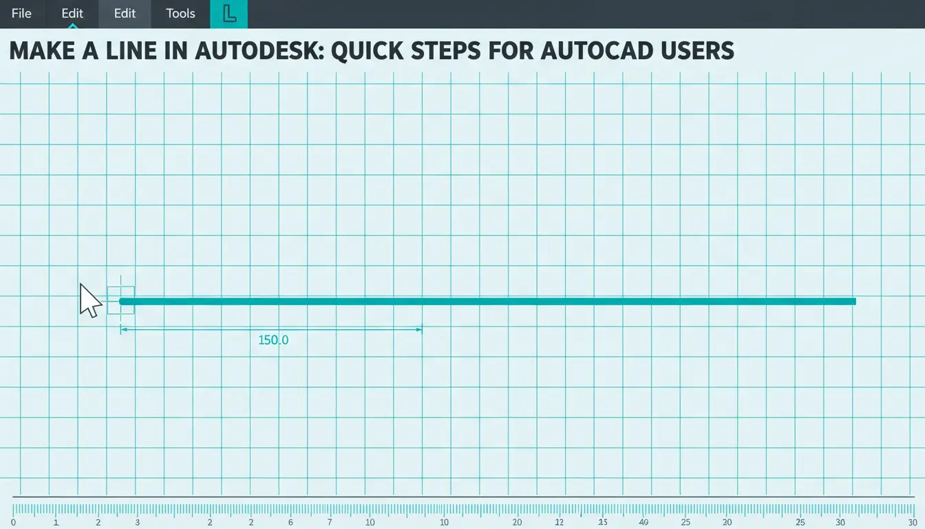
To make a line in Autodesk is to place the simplest drawing primitive: a straight segment defined by a start point and an end point. Lines form the backbone of precise drafting — they convey geometry, establish limits for trims and joins, and serve as the building blocks for polylines, hatches, and construction geometry. When you draw a line you control its exact location with coordinates, object snaps, or dynamic input, and you assign properties such as layer, color, linetype and thickness so it behaves predictably in drawings and sheets.
Understanding line basics speeds later editing: trimming, extending, filleting, or converting single segments into polylines are routine once the initial placement is accurate. Use grid, ortho mode, and polar tracking to enforce orthogonality and angles; use object snap and coordinate entry for absolute precision. For more on the dedicated drafting tools most users rely on, see the AutoCAD overview on SoftAuthentic.
If you need official product details about capabilities and supported workflows, consult Autodesk’s AutoCAD overview for examples of line tools and precision drafting features.
Begin the LINE command, click or enter the start coordinate, then click or enter the end coordinate — that single action creates a segment. You can continue clicking to add chained segments, or press Enter/ESC to finish. For precision, type absolute coordinates (x,y) or relative coordinates (@dx,dy); enable ORTHO for straight horizontal/vertical lines or POLAR for constrained angles. Object snaps (endpoint, midpoint, intersection) let you attach lines exactly to existing geometry, while Dynamic Input displays coordinates and lengths near the cursor for real-time feedback. After placement, use grips or edit commands (stretch, trim, extend, lengthen) to refine the line without redrawing. Mastering these simple steps makes later modeling and documentation much faster and more accurate.
To make a line in autodesk you should begin by launching AutoCAD or AutoCAD LT and opening a new drawing or an appropriate template. Proper setup prevents scale and snapping surprises: start the program, choose a template that matches your discipline (metric or imperial), then run the UNITS command to set the unit type and precision. Next, set drawing limits or the drawing extents so the grid and snap spacing behave predictably, and confirm the insertion units to match any blocks or external references you’ll use. Turn on orthogonal (ORTHO) or object snap (OSNAP) modes according to the geometry you’ll draft. If you rely on annotation, enable Annotative scaling for text and dimensions and set a default annotation scale in the status bar. Save this configuration as a template if you’ll reuse it.
Need the software or more product details? See the AutoCAD product page for features and licensing options and SoftAuthentic’s AutoCAD listing for purchasing information.
Quick checklist before drawing a line: 1) Type UNITS → choose Decimal/Architectural and set precision. 2) Set drawing limits (LIMITS command) to the real-world paper or model extents and run ZOOM → A to fit. 3) Verify insertion units so imported geometry scales correctly. 4) Choose a working scale: if you plan to plot at 1:50, design in model units that correspond to the scale or use viewports with the correct viewport scale. 5) Confirm snap spacing and OSNAP settings so your first line snaps to intended points. With these steps your lines will have the correct length and will snap, dimension, and plot predictably.
Before you draw, set your workspace to Drafting & Annotation so the Line command and coordinate entry fields are prominent. Open the UNITS dialog to choose metric or imperial — picking the right unit system up front avoids scaling errors when you specify coordinates or lengths.
Enable the grid and Object Snap (OSNAP) for cleaner layouts: grid gives visual spacing, Snap restricts cursor movement to set intervals, and Polar Tracking helps you lock angles while drawing lines. For precise coordinate entry, use absolute (x,y) or relative (@dx,dy) formats directly in the command line; this is especially helpful when you need exact endpoints.
For a quick reference on AutoCAD workflows, see this AutoCAD guide and the official Autodesk AutoCAD product page.
To make a line in Autodesk, activate the Line command by typing LINE or L at the command prompt, or by selecting the Line tool on the Home ribbon. Click the start point in the drawing area, then click the end point to draw the segment; repeat clicks to chain segments. Press Enter or Esc when you’re finished to exit the command.
LINE or L, or click the Line icon on the ribbon.Tips: enable Object Snap (OSNAP) for precise endpoints, midpoint, or intersection placement; toggle Ortho mode to constrain lines to 90°; use Polar Tracking to snap to common angles. If you need a quick reference to advanced drafting workflows, visit the Autodesk AutoCAD product page or Autodesk’s official AutoCAD overview for feature details.
When precision matters, enter coordinates directly: absolute (x,y) or relative with an @ prefix. For example, click a start point and type @5<30 to draw a 5-unit line at 30 degrees from the previous point. Use object snaps like Endpoint, Midpoint, and Perpendicular to lock onto existing geometry. If you misplace a point, use the command’s Undo option or press Esc to cancel and restart. Check your drawing units before placing critical geometry so length and angle entries behave as expected. These small habits make drawing reliable and efficient when you need to make a line in Autodesk quickly and accurately.
While the Line command is active you can type absolute coordinates (x,y) into the command line, or precede values with @ to enter relative distances. Press C to close a polyline and connect back to the start point, which is useful for creating closed shapes quickly. Holding Ctrl temporarily constrains movement to orthogonal directions if your settings support it; alternatively use Ortho mode for a persistent orthogonal snap.
Other quick tips: type Undo to remove the last segment, use direct coordinate entry for precision, and watch the dynamic input prompts for angle and length. These small shortcuts speed up drafting and are applicable across most AutoCAD workflows.
For a concise overview of drawing tools see AutoCAD tools and commands, and for official product details visit the AutoCAD product page.
When you need to make a line in autodesk with precision, enter absolute coordinates (x,y) or use relative coordinates with @dx,dy to build chained segments from the last point. Absolute coordinates place points exactly on the drawing’s coordinate system—typing 12.5,7 puts a point at X=12.5, Y=7. Relative entry begins with @ and measures from the previous point, so @3,-2 moves 3 units right and 2 units down from wherever you last clicked. Use decimals and negative values freely; the command accepts them directly.
This approach is essential for drawings that require exact placement, repeated offsets, or when you’re scripting sequences of connected segments. Remember to check your UCS (User Coordinate System) and object snaps so coordinates reference the correct plane and geometry. For a quick refresher or to obtain AutoCAD tools that support these workflows, see the Autodesk AutoCAD resources at SoftAuthentic.
Start the LINE command (type LINE or L, then Enter). For an absolute start point, type x,y (for example 10,5) and press Enter. For the next point, either type another absolute pair (20,5) or a relative entry like @10,0 to go 10 units right from the last point. To draw at an angle using polar entry, use @length When you need to make a line in autodesk with reliable geometry, the combination of Object Snaps, Ortho and Polar Tracking is the fastest route to accuracy. Turn on Object Snaps (OSNAP) — F3 — and enable the running snaps for Endpoint, Midpoint and Intersection so your cursor locks to existing geometry. Use the Object Snap settings dialog to prioritize which snaps run and to avoid conflicting pick points. Enable Ortho (F8) when you want strictly horizontal or vertical segments; it constrains your cursor to 0°/90° while drawing. For angled work, enable Polar Tracking (F10) and set the angular increment (for example 15° or 45°) in the drafting settings. Together these tools remove guesswork: start the LINE command, hover near a snap point until the marker appears, click to anchor, then rely on Ortho/Polar for the next vertex. Access these toggles from the status bar or the Drafting Settings dialog, preview snap markers, and for precise distances use relative polar entry (for example @100<30) while Dynamic Input displays coordinate prompts. If you need configuration help or a local installer, see the AutoCAD details page for downloads and licensing. For a quick reference to commands and tool locations, see the AutoCAD overview. To make a line in Autodesk reliably, configure running object snaps and use Ortho/Polar to control direction. Start the LINE command, then rely on Endpoint, Midpoint and Intersection snaps to lock to existing geometry for precise start and end points. Workflow tip: keep running snaps on for speed, and toggle Ortho or Polar with the function keys as you draw to switch alignment without leaving the Line command. For more on purchasing or downloading AutoCAD, see the AutoCAD product page, or read the official Autodesk AutoCAD overview for feature details. After you draw a line, use grips, the Move/Trim/Extend tools, and the Properties palette to refine geometry quickly and non-destructively. Click a line to show grips (blue squares) — click a grip once to move the endpoint, or click again to access stretch, rotate, scale and mirror options. For precise repositioning, run MOVE and pick a base point, or use ORTHO and object snaps (Endpoint, Midpoint) to lock direction and accuracy. Trim and Extend are ideal for cleaning intersections: Trim removes excess, Extend lengthens to a boundary. Use selection fences or SHIFT to pick multiple segments. When you need uniform edits across many objects, change properties from the Properties palette (layer, color, linetype, lineweight) rather than editing each entity. Organize lines by assigning them to named layers with distinct colors, linetypes and weights. Set a layer as current before drawing to ensure new lines inherit those attributes, or select existing lines and change their Layer property to move them between layers. Control visibility and plotting with layer Freeze, On/Off and Lock—freeze for performance, off for simple hide, lock to protect geometry. Save common configurations with Layer States for repeatable setups. For more AutoCAD-focused workflows and downloads, see this AutoCAD resources page. When you make a line in autodesk, create or choose a layer first (color, linetype, lineweight) so the line adopts those visual controls automatically. If you’ve already drawn the line, select it and change its Layer in Properties; change Color or Linetype there if needed. Use layer filters to find specific groups quickly, and toggle plot visibility for presentation-ready drawings. For official product documentation and advanced tips, visit the Autodesk product page. When you try to make a line in autodesk and it doesn’t show up, stay calm — most issues are visibility or coordinate-system related. First, confirm the layer you’re drawing on is thawed, unlocked and has a visible lineweight and color; frozen or off layers are the single most common cause of invisible geometry. Use Zoom > Extents (or type Z then E) to reveal objects that may be far from the current view. If objects still don’t appear, check Draw Order (bring to front) and use REGEN to refresh the display. Undo (Ctrl+Z) is your fastest recovery from accidental operations. If dimensions look wrong, verify drawing units (UNITS) and the current UCS — a rotated UCS or mismatched units will make lengths appear incorrect. For precision issues check OSNAP and SNAP settings, and use LIST or PROPERTIES on a selected line to confirm coordinates and length. If you suspect the object is a block, explode or examine block geometry. For an in-depth reference on AutoCAD features see the AutoCAD product page at SoftAuthentic, and for official product details visit the Autodesk AutoCAD overview. Start with these targeted steps: 1) Hit Ctrl+Z if you just lost progress. 2) Type LAYER and ensure the target layer is On/Thawed and not frozen. 3) Use Zoom Extents to find off-screen geometry. 4) Run REGEN and, if necessary, PURGE to clean display clutter. 5) Check UNITS and UCS if lengths look wrong; switch to World UCS to test. 6) If snapping fails, toggle OSNAP or set a running object snap. Finally, use QSELECT or FILTER to locate stray line objects by layer or color. These quick checks resolve most “invisible line” and measurement problems. When you try to make a line in autodesk and something goes wrong, start simple: press Ctrl+Z or type UNDO to step back, then use ERASE to remove stray entities. Layer visibility and locking are frequent culprits — open the LAYER palette, thaw and turn on suspect layers, and unlock any locked layers before re-drawing. If geometry seems to vanish, run ZOOM EXTENTS to bring off‑screen objects into view; extremely large coordinates can place lines far from the origin. Check the current UCS and confirm coordinates with LIST or ID, then MOVE or ALIGN mislocated objects back to expected positions. Use REGEN if the display seems stale, and review layer plot/freeze settings if objects are invisible in prints. For a deeper walkthrough of core tools, see the AutoCAD basics guide. For official documentation and product details, visit the Autodesk AutoCAD overview.Precision: snaps, ortho and polar tracking
How to make a line in autodesk: quick steps
@50<45 for 50 units at 45°.Object snaps and ortho mode
make a line in autodesk
Editing lines and working with layers
make a line in autodesk: assign layers and tweak properties
Tips, common mistakes and troubleshooting
make a line in autodesk — quick fixes
Undo, erase and layer visibility fixes
make a line in autodesk — quick recovery



 Autodesk
 Design Softwares
 CorelDraw
 Affinity V2
 Microsoft & Windows
 Windows
 Microsoft 365