- Instant email delivery
- Global licenses
- Secure checkout
- 24/7 customer support
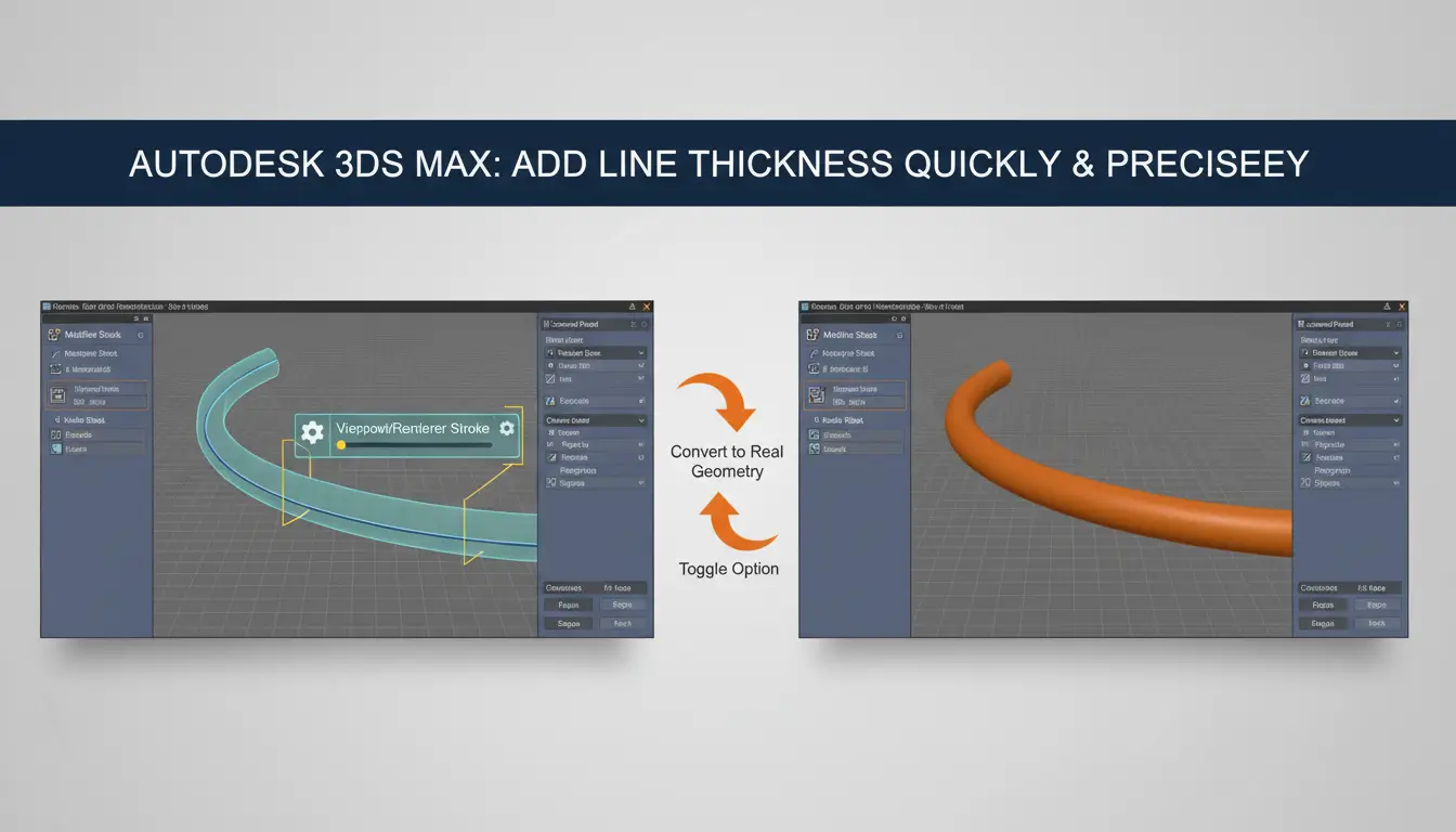
In autodesk 3dsmax, “adding thickness” to a spline has two distinct meanings that affect workflow and deliverables. One approach adjusts a spline’s visual stroke — changing how wide a line appears in the viewport or in a render — without creating new polygons. The other produces real 3D volume by converting or modifying the spline into mesh geometry. Choose based on whether you need simple presentation, animation-friendly topology, or clean exportable models for other DCC tools or game engines. For a quick reference to related Autodesk tools and licensing choices, see the Autodesk products page.
Visual stroke methods are fast: many renderers let you render splines as thick lines or hair-like primitives, which is ideal for concept visuals, technical illustrations, or when topology and collisions aren’t required. They keep scene size small and are easy to animate because they don’t add faces. By contrast, using modifiers like Extrude, Sweep, Lathe or Shell (or converting to editable poly and capping) creates real geometry with faces, UVs and normals — necessary for realistic shading, physics, deformation, or reliable exports to other software. If you plan to simulate, 3D print, or hand off assets, generate solid geometry. For official reference and renderer compatibility notes, consult the Autodesk official site.
autodesk 3dsmax treats lines, splines and shapes as 2D curve objects that live in the scene as parametric outlines. They have a separate Rendering Thickness parameter (and a “Renderable” toggle) which affects only how they appear at render time or when you enable renderable spline settings — it does not create true volumetric geometry for physics, booleans, or export. Use these objects for profiles, paths, text and guides because they’re lightweight and infinitely editable without adding polygonal complexity.
By contrast, Editable Mesh and Editable Poly are full 3D, face/edge/vertex-based geometry. They represent real triangles/quads in the scene, so if you need physical thickness, collisions, or precise UVs you must create volume explicitly: convert a spline with Extrude/Sweep/Lathe, or add modifiers like Shell, Extrude or Boolean to a mesh/poly. Editable Poly offers rich modeling tools (edge loops, bevels, polygon-level edits, smoothing groups) that make it the preferred target for final models.
Practical rule: keep shapes as splines for parametric control and only convert or apply volumetric modifiers when you need real geometry. This keeps your modifier stack clean and performance friendly. For more downloads and licensing information see SoftAuthentic’s Autodesk page, or visit the Autodesk official site for product details.
When starting, sketch with splines and enable “Renderable” or use Sweep/Extrude modifiers when you need visible volume while preserving the original curve. If the object must interact as a solid (booleans, game export, physics), convert to Editable Poly or use the Shell modifier to add true thickness. Keep modifier stacks nondestructive while iterating, then collapse to Editable Poly for final cleanup: fix normals, assign UVs and apply smoothing groups. This approach balances flexibility, performance and the final asset requirements.
autodesk 3dsmax provides a quick, non‑destructive way to thicken spline strokes by using the spline’s Rendering (or Renderable Spline) Thickness setting. This approach gives immediate viewport feedback and renders solid-looking strokes without creating extra geometry, making it perfect for technical illustrations, CAD-style linework, and annotated visuals where you want precise, editable strokes.
Workflow is simple: select the shape, open the Modify panel, locate the Rendering/Renderable Spline rollout, enable rendering, and set the Thickness value. Toggle the viewport preview option to see results in real time, and increase Segments or Sides to smooth round strokes. You can animate the Thickness parameter or drive it procedurally for varying line weights.
Because you keep the spline as an editable object, scene complexity and memory use stay low and animation rigs remain easier to manage. Note the tradeoff: spline-based thickness is ideal for orthographic and stylized renders but may not behave exactly like extruded mesh for complex shadowing, booleans or physics—convert to mesh when you need full geometric fidelity.
For official product references visit the Autodesk website, or see a broader list of Autodesk apps and licenses at this Autodesk apps directory.
Use low Segment counts for crisp technical strokes and higher counts for smooth circular profiles. If you see faceting at large Thickness values, raise Sides/Segments or apply a small smoothing modifier after converting to mesh. For viewport performance, keep the preview enabled only when adjusting and turn it off for heavy scenes. When exporting linework for vector output, render at higher resolution or convert strokes to geometry first to preserve exact line weights. These small adjustments let you leverage spline rendering thickness for fast, clean technical results without unnecessary geometry.
If you need a solid-looking spline in autodesk 3dsmax, follow these quick steps to enable and control Thickness so it appears in the viewport and renders correctly.
Tip: perform a quick production render to verify light and shadow on the thickened spline. For related Autodesk resources, see the SoftAuthentic Autodesk page and the official Autodesk website.
In autodesk 3dsmax the Extrude modifier is the quickest way to turn a 2D spline into true solid geometry with depth—perfect when you need meshes for lighting, collision, or export. Draw your spline (open or closed), apply Extrude from the Modifier list, set the Amount for thickness and increase Segments for cleaner shading. Toggle Caps to close ends and use Flip normals if faces point the wrong way. Work non‑destructively in the Modifier Stack and only convert to an Editable Poly when you must edit topology or unwrap UVs. For specialized profiles combine Extrude with Bevel or Sweep. Before exporting, run a quick weld, check smoothing groups, and create a simplified collision mesh where appropriate. For related software bundles and licensing see the Autodesk Media & Entertainment offerings and consult the official Autodesk website for product details.
Autodesk Media & Entertainment offerings · Autodesk official website
Step-by-step: create a spline (Line, Rectangle, Circle), select it and add Extrude from the modifier list. Set Amount to the desired thickness and raise Segments if you need smoother caps or curved profiles. Enable Caps to seal ends; use the Bevel angle or Profile where available for stylized edges. If shading looks off, check and flip normals, or assign smoothing groups. When ready to finalize, convert to Editable Poly, clean up stray verts, chamfer sharp edges, then apply a TurboSmooth only if topology supports it. For game-ready assets, keep a separate low‑poly collision mesh and triangulate or bake normals as required. If you already have a mesh and need thickness, prefer Shell instead of Extrude. Remember to Reset XForm before export to avoid transform issues in downstream tools.
In Autodesk 3dsmax the cleanest workflow is simple and predictable. Start by ensuring your spline is closed and has the intended pivot and scale. Converting to an Editable Spline is optional but useful if you need to clean up vertices or weld segments before extrusion.
Quick tip: keep a backup of the spline before collapsing. For more on Autodesk tools and licensing, see the SoftAuthentic Autodesk page and the official Autodesk product pages.
autodesk 3dsmax offers the Sweep modifier as a straightforward way to sweep a custom cross‑section along a spline, giving you full control over rounded, beveled or variable-width strokes. Start by drawing a clean profile (circle, rounded rectangle, or custom spline) and position it at the spline’s start. Apply the Sweep modifier to that profile and use the Pick Path button to choose the curve you want to follow. Use alignment, banking and twist controls to orient the profile, and tweak Start/End Scale or Steps to refine the look. For final cleanup convert to an editable mesh, set smoothing groups, and add caps or bevels as needed. For a broader selection of Autodesk tools and resources, see the Autodesk software catalog.
Keep the profile closed for solid geometry and avoid self-intersections in the path. If you need varying cross-sections along the length, consider using Loft (which supports multiple shape sections) or stack multiple Sweep modifiers with different profiles for procedural control. Use low Step counts for previewing, then increase subdivisions for production renders. To maintain consistent UVs, apply a UVW Map modifier after converting to mesh, and use smoothing groups or a turbosmooth modifier only after setting hard edges where needed. If you want official reference for tool behavior and parameters, consult the Autodesk official site.
Sweep is ideal when you need to create consistent cross-sections along a path — pipes, rails, trim, or custom mouldings. Use it when a simple extrusion or loft can’t give the exact profile orientation or when you want quick, editable geometry along a spline.
For smoother results, increase segments or enable adaptive steps and check caps if you need closed ends. For more on modifier workflows, see the official Autodesk site or browse related tools at SoftAuthentic Autodesk.
If you already have thin geometry, applying a Shell modifier or using Edit Poly with extrude/offset tools are the fastest ways to give it solid thickness without rebuilding the mesh. Start by checking normals and making sure the mesh is watertight—open edges and flipped normals will produce holes or inverted shells. Shell is non‑destructive and ideal when you want uniform inner or outer wall thickness: add the modifier, set Inner/Outer amounts, and enable Cap if needed. Because it sits in the modifier stack, you can tweak thickness later and combine it with smoothing or chamfer modifiers for crisp edges.
Edit Poly is more manual but gives targeted control: select face islands and use Extrude or Extrude Along Normals, or use Inset + Extrude for cleaner offsets. For thin, multi‑panel models, use Vertex Weld and Turn to clean topology after extrusion. If you need to preserve edge loops for subdivision, inset the faces first and then extrude to avoid pinching. Before finalizing, collapse the stack and run a Reset XForm if export problems appear.
These approaches are common in production and prototyping workflows; for other Autodesk product options and bundles see the site’s Autodesk software listings for licensing and package details.
Shell is the go‑to when you want a fast, consistent wall thickness with minimal topology work; it’s perfect for architectural panels, props, or parts that don’t need new edge loops. Edit Poly is preferable when you need variable thickness, precise caps, or when preparing a mesh for 3D printing or simulation—it gives control over face‑by‑face extrusion and supports custom bridging and welding. Watch for self‑intersections when extruding complex concave regions and run a quick mesh integrity check. For official product info and tutorials, consult the Autodesk website.
When using the Shell modifier on a single-sided surface in 3ds Max, set the Outer Amount and Inner Amount explicitly instead of a single thickness value. For open meshes, keep one side at 0 and the other positive so you don’t create inverted faces. Check and correct normals and smoothing groups before shelling — use Normal or Auto‑Smooth to prevent shading artifacts. Unwrap UVs or apply a UVW Map first so textures don’t stretch when the surface expands. If you want rounded edges, place TurboSmooth after Shell and add support loops or crease edges to retain definition. If faces appear inside out, flip normals or collapse the stack once appearance is confirmed. For concise tutorials and related downloads, see the Autodesk resource hub and the official Autodesk website.
When working in autodesk 3dsmax, remember that viewport stroke thickness often differs from rendered or exported geometry. Many spline-based strokes are rendered as screen-space thickness or as shader effects and won’t become real volume when you export to OBJ/FBX. If you need physical geometry for 3D printing, game engines, or interchange, convert splines into mesh using Extrude, Sweep, or Shell modifiers rather than relying on viewport display alone.
Before export, collapse or bake modifiers where appropriate and reset XForm to avoid scale/rotation issues. Flipped normals, duplicated vertices, and inconsistent smoothing groups are common culprits for rendering artifacts or invisible faces in other applications—use the Normal and Unwrap utilities to inspect and correct them. Adding a small bevel to critical edges improves shading and reduces hard seams.
Performance-wise, thickening many lines can quickly bloat polygon counts. Combine similar splines, instance repeating elements, or limit conversion to only the lines that truly require geometry. For interactive previews, use lower-segment sweeps and increase resolution only for final exports. If you work across Autodesk apps, consult the Autodesk product listings for compatible workflows: Autodesk product listings.
Export early and verify in a neutral viewer to catch topology and UV issues before final delivery. For exporter updates and official guidance, see the Autodesk official site: Autodesk official site.
Start by cleaning the spline: weld vertices, remove duplicate points, and ensure continuous segments. Apply a Sweep or Extrude modifier to give true volume; Shell is useful for turning a thin surface into two-sided geometry. Keep segment counts low during iterations, then increase segments for final export. After conversion, run Reset XForm, collapse the stack, and check normals—use “Flip” or “Unify” as needed and assign smoothing groups to control shading. If exporting many thickened lines would hurt performance, consider baking visual thickness into normal maps or using impostors for distant objects. Finally, run a quick tri/quad check and export a lightweight sample to validate the target pipeline before committing to large batches.



 Autodesk
 Design Softwares
 CorelDraw
 Affinity V2
 Microsoft & Windows
 Windows
 Microsoft 365